


The Transistor
Transistors can be regarded as a type of switch, as can many electronic components. They are used in a variety of circuits and you will find that it is rare that a circuit built in a school Technology Department does not contain at least one transistor. They are central to electronics and there are two main types; NPN and PNP. Most circuits tend to use NPN. There are hundreds of transistors which work at different voltages but all of them fall into these two categories.
 The leads on a transistor may not always be in this arrangement. When buying a transistor, directions will normally state clearly which lead is the BASE, EMITTER or COLLECTOR.
In each of the manufacturing rooms there are display boards, this one shows the LED and the Transistor.
 The Resistor

 Resistors determine the flow of current in an electrical circuit. Where there is high resistance then the flow of current is small, where the resistance is low the flow of current is large. Resistance, voltage and current are connected in an electrical circuit by Ohm’s Law.

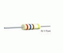
 Resistors are too small to have numbers printed on them and so they are marked with a colour of coloured bands. Each colour stands for a number. Three colour bands shows the resistors value in ohms and the fourth shows tolerance. Resistors can never be made to a precise value and the tolerance band (the fourth band) tells us, using a percentage, how close the resistor is to its coded value. The resistor on the left is 4700 ohms.
There is also a resistor display board in each of the manufacturing rooms and on this one there is a close up of a resistor showing the colour code and the inside.
An L.E.D. (Light Emitting Diode)

 Light Emitting Diodes (LED) are very rugged, they last a very long time and they are an optical source. (A LIGHT SOURCE)
LEDs produce red, green, yellow, or orange light. They are used in a range of products.
Can you name any?

 LEDs are part of the diode family, consequently they must be connected the right way round or current will not pass through. They are usually protected by a resistor.
This display also shows the LED and give a description, there is also a resistor model which clearly shows the different lengths of the legs. The long one being the positive and a red lead is soldered onto it and the shorter one is the negative and has a black lead soldered onto it. If you look closely at the led you will see a flat part on the side, this is another way of identifying the negative leg if the have been cut.
The Thyristor
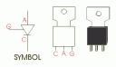
A Thyristor (silicon controlled rectifier or SCR) is a little like a transistor. When a small current flows into the GATE (G), this allows a larger current to flow from the ANODE (A) to the CATHODE (C). Even when the current into the gate stops the thyristor continues to allow current to flow from anode to cathode. It latches on.
The circuit below represents a steady hand game, which consists of a wire loop that has to be moved around a wire course without touching it. If the wire course is touched by the loop, current flows into the ‘gate’ of the thyristor and the buzzer (or in the case of your project the LED stays on) sounds.
The buzzer will continue to sound after the loop has touched the wire course. This is due to the thyristor which once activated cannot be deactivated until all power is turned off.
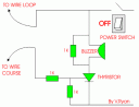
This type of circuit is also known as a ‘latching circuit’

For our first year Tech exams Tomorrow do we need to know about the ‘Thyristor’ ?
Only if you used it in class. CTD
diz realy helped me wid ma exam!!
Glad this helped with th exams. CTD
this really helps me for revising on!! 🙂
I Love dis its thee Bestest Ever it helped mee so much and im Ever so thankful…
all my life i have been waitin for help and finally i hve some.
ThankYou this has helped…
Clounagh has bettr Technology Rooms
Than Ballymena… =)
a bit drmatic louis! but this iste does rock